Abstract — This paper explores the various design elements of off-pavement and on-pavement standards and changes to U.S. and international highway design policies over the latter-half of the 20th century that contributed to a major reduction in automobile fatalities. It explores the policy, geometry, and expansion of roadside hardware. It then demonstrates that these changes do correlate with a reduction in highway fatalities.
DEVELOPMENT OF ROADSIDE SAFETY
The Human Factor
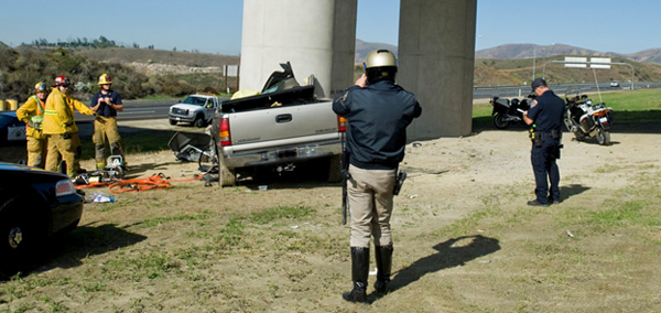
Perhaps only the family of Jay Winters knows why he decided to take the toll road that Monday morning in early December 2010. Winters entered California Highway 241 southbound through Trubuco Canyon, California toward Irvine. As he approached a split with a second toll road, Winters’ late-model Chevy pickup drifted halfway across the road’s spacious 130-foot-wide median where it collided with a bridge pillar at freeway speed. First responders believe Winters probably died on impact [1]. Photos show the crash (Figure 1) was so severe, only the rear tailgate was undamaged.
Gratefully, highway fatalities like this one are becoming less common than they were decades ago. Much of that is a credit to improved vehicle crash protection, including crumple zones, air bags, and rollover protection. The highway itself is becoming safer, too, thanks to a conscious effort by road designers to add forgiving features to today’s modern highways.
The Forgiving Roadside
In the middle of the 20th century, road designers paid little attention to off-pavement design. They viewed an ideal world where highway engineers would never need to look beyond the asphalt when designing a road, as motorists would never accidentally leave it.
The Transportation Research Board (TRB) is part of the U.S. National Research Council, who serve as advisers to the President, Congress, and federal agencies when it comes to making policy decisions about transportation. In a recent publication, they addressed old attitudes:
“Engineers seemed to shrug collectively and matter-of-factly proclaim that they designed roads to drive on, and had no responsibility toward [a] driver who could not keep his vehicle on the road.” [2]
Today, the area outside of the pavement is as important as the design of the highway itself. The Federal Highway Administration (FHWA) regularly releases safety memoranda. Many of these require states to take prompt action to ensure safe roadside hardware and off-pavement design to keep motorists safe.
The American Association of State Highway Transportation Officials (AASHTO) offer design manuals to help make new roads and refurbished roads safe. These manuals include “A Policy on Geometric Design of Highways and Streets” (known as the “Green Book” for its green cover) and “Highway Safety Design and Operations Guide” (known as the “Yellow Book”, also for the color of its cover).
OFF-PAVEMENT SAFETY DESIGN
Assessment Practices
A piece of roadside safety hardware is only as safe as it has been designed to be safe. In 1962, the American Association of State Highway Transportation Officials (AASHTO) established testing criteria to create a unified methodology for making sure hardware performed in a safe manner. [3] American transportation officials worked with their European counterparts to create more unified standards across both continents in the early 1990s.
In the most-recent version of the Manual for Assessing Safety Hardware (MASH), test procedures were updated to reflect the mass and shape of the 85th percentile of U.S. passenger fleet, including changing the angle a car was crashed. Subjective criteria were better defined, and a few inconsistencies in previous test procedures were corrected. [4]
Forgiving Design
Ideally, a vehicle should never leave the pavement. Proper road design should facilitate that goal. When a motorist does lose control of a vehicle, a highway’s design can play a critical role in preventing a crash or reducing its severity. These design factors take into account speed, curve and turning radius, providing an adequate horizontal clear zone, and vertical embankment.
Design Speed
Design speed is regulated by roadway geometry standards set by AASHTO “A Policy on Geometric Design – Highways and Streets” (“Green Book”). A safe speed for a highway is determined by physical characteristics of the highway, the amount of roadside interference, weather, and presence of other vehicles [5]. These design factors help set a safe speed limit for when conditions are favorable, including sight distance, super-elevation, and turning radius.
Vertical and horizontal sight distances take into account a driver’s ability to spot an obstruction and safely react to it. This includes reaction time.and it takes into account the distance needed for stopping at design speed on both horizontal and vertical curves, the distance required for safely passing a vehicle, and sight distance in complex locations [6].
Curve Radius
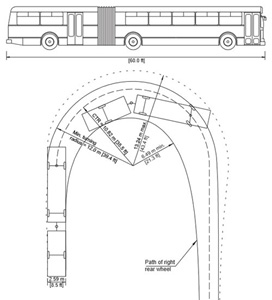
Turning radius takes into account the design speed of the road making sure the vehicle’s inertia does not exceed the side friction forces which give a vehicle traction to stay in lane and not leave the pavement [7]. It also takes into account the type of vehicle using the road. A road used only by passenger cars may safely navigate a corner with a 24-foot turning radius, while an articulated bus may need a 40-foot turning radius (Figure 2). An inadequate turning radius may result in a vehicle leaving the pavement [8] which cause safety issues for the vehicle itself. Any traffic following the vehicle may have to suddenly brake or swerve off the pavement.
Super-elevation of roadway curves act as a vertical banking which assist higher-speed vehicles to turn a corner more easily and stay in their lane. Super-elevation takes into account the friction of the pavement, radius of the curve, design speed of the road, type of vehicle using the road, and the climate of the area where the road is being built. For instance, in icy climates a super-elevation that is too steep can allow a car to slide off the pavement, or train motorists to enter the curve at speeds too fast for the weather. While a super-elevation of 12 percent may be used it should be reduced to 8 percent or less in icy climates [9].
Lane Width
How wide a travel lane is has an influence on crash susceptibility [10]. Wider lanes offer extra space for motorists to swerve around an in-lane obstruction without leaving their travel lane. If every travel lane is wider, the sum of extra space acts as a buffer. When a vehicle swerves this buffer gives assurance to other motorists that the swerving vehicle has space without having to enter their lane. This prevents additional loss of control situations that could send any of these vehicles off the pavement.
Hard Shoulder
A hard shoulder offers a few extra feet of paved recovery space. This is valuable for a motorist who needs to recover an out-of-control vehicle. It can also double as on-street parking or snow storage in the winter.
Horizontal Clear Zone
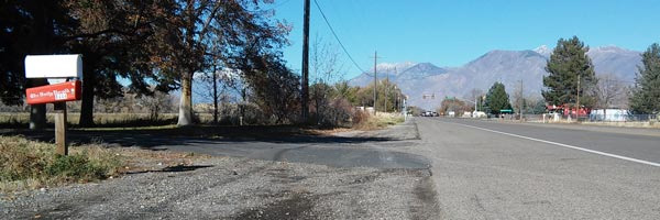
A formula in the AASHTO “Green Book” calculates the amount of obstruction-free “clear zone” space recommended. This is measured from the outside lane marking. Clear zones give motorists of an out-of-control vehicle space to recover without striking an object. The clear zone varies in design width and takes into account factors like speed, traffic volume, and embankment slope (Figure 3).
When constraints prevent a full design-width clear zone, a reduced-sized clear zone should adopt as many safety concepts as practical [11] [12]. These concepts include: removing an obstacle inside a design clear zone, moving the obstacle farther from the pavement’s edge to reduce its chances of being struck, add breakaway devices to reduce the severity of the crash, shield the object with a barrier, or mark the object with a reflector [11].
Internationally, clear zones vary from country to country. They vary from as short as 0.5 meters in the Czech Republic, on both highways and urban streets, to over 30 feet along United States freeways [2].
Shoulder Embankment Slope
In non-urbanized areas or in areas without substantial vertical changes, such as cliffs, bridges, or ledges, it may be appropriate for a highway to offer no barrier protection at all. Instead, a highway’s off-pavement grade can, in itself, offer adequately reasonable protection for a motorist who leaves the pavement’s edge.
According to AASHTO’s “Yellow Book,” which addresses highway safety on existing and future roadways, “there is a growing realization… that side slopes on embankments and in cuts should provide reasonable opportunity for recovery for an out-of-control vehicle.” [13]
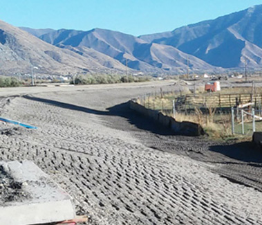
Ideally a slope should be as flat as possible. As a slope becomes steeper a vehicle increases its chance of tipping over and rolling, causing a crash. The Yellow Book suggests a maximum slope of 1:6 (Figure 4[Field]) on arterials and highways, although slopes as steep as 1:3 can be driven on as long as they are smooth and unobstructed. Adding in runout areas, to gently curve the existing ground into the slope is very important in preventing a crash. [2]
The 1:6 slope standard isn’t universal in all countries. Embankment varied from as low as 1:1 in China, even along the edge of highways. Throughout much of Europe acceptable maximum slope can vary from 1:2 to 1:3. It is acceptable in Greece to set the slope as steep as 2:3 [14].
Forgiving Hardware
In addition to proper road design, physical pieces of hardware along the roadway’s edge can help keep motorists and passengers safe when driver error, inclement weather, or improper design lead to an out-of-control vehicle. Available hardware includes longitudinal barriers, energy absorbing barrier terminals, curbs, breakaway sheer bolts, and advanced warning signs.
Longitudinal Barriers
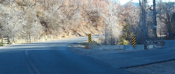
When properly designed, a longitudinal barrier protects a motorist from a rigid object, drop off, or other obstacle which could lead to a fatal crash. When improperly designed, a longitudinal barrier can become an obstruction (Figure 5).
Jersey Barriers
The easiest solution to prevent a vehicle from leaving the roadway is to place a barrier, be it concrete or a steel W-rail, to prevent the car from leaving the roadway. Barriers do not exist on the edge of every road because the benefit from preventing the car from leaving the pavement needs to outweigh the certain crash of colliding with the barrier itself.
Jersey barriers, also known as “K-Rail” by the California Department of Transportation, is shaped to feature a shallow slope at the base of the barrier and a steeper slope higher up (Figure 6).
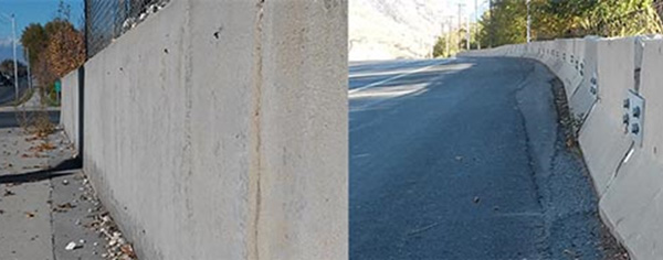
The shape allows a vehicle’s tires to drive onto the barrier to reflect the vehicle’s inertia forces back toward traffic. It was first rolled out by the state of New Jersey (hence the term “Jersey Barrier”) in the mid-1950s and has been modified every few decades since [15].
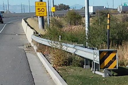
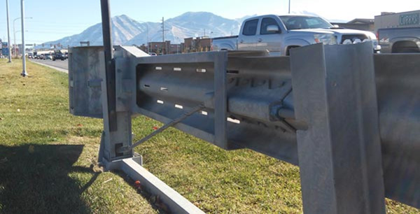
These barriers are designed with sloped ends which reduce crash severity in slower-speed applications. They do require special attention when roads have higher speeds to absorb and deflect the shock of a collision, which may ideally use a combination of W-beam with a shock-attenuating terminal (Figure 8).
W-Beam
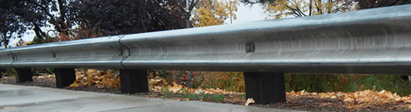
“W-beam” is a nickname given to a specific type of strengthened, crashworthy steel that is constructed into a guardrail that is mounted longitudinally along the side of a highway. It is used to prevent vehicles from crossing into on-coming traffic, driving into rigid or dangerous roadside objects, or as a crash cushion transition into a Jersey barrier. W-beam barriers are mounted to posts on the edge of a roadway (Figure 7).
Unlike Jersey barrier, which sits directly on the ground, W-beam barriers mount to 6-by-8 inch wooden posts. Steel posts can be used if they are rated as crashworthy [16]. FHWA requires all W-beam barriers be mounted no lower than 27 ¾ inches to the top of the rail. Older designs with shorter rails need to be retrofitted. Some new modern designs raise the W-beam to 31 inches. These specific heights were designed to best contain and redirect passenger cars (27 ¾ inches) but SUVs and light trucks catch better at 31 inches under MASH testing [17].
A contractor installing a W-beam must take great care to ensure the steel’s integrity isn’t compromised. For instance, if the manufacturer-drilled holes do not align with other hardware, such as posts, the contractor is severely warned not to drill additional holes [16]. If a barrier has been bent in a crash, it should never straightened, nor reused, nor should salvaged posts or rail be used in other projects or repairs [16].
Removing Flares and Turn-Downs
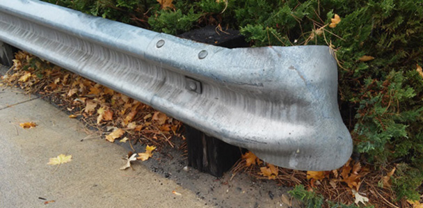
Traditionally, many W-beam guardrails offered little-to-no protection at the terminating upstream edge of the guardrail. Designers seemed to settle for simply flaring (Figure 9) the end. It offers some aesthetic value, but does not offer any protection for motorists at travel speeds.
Prior to research, flaring the end was considered adequate for many years. In 1964, the National Research Council of the Highway Research Board stated:
“The approach end of guardrail installations normally should be flared… until further research leads to a better design, the flared-and-anchored arrangement is recommended, particularly on high-speed facilities.” [18]
The trouble was, at nearly every speed – but especially at highway speed — a blunt or flared end acts as a javelin and pierces into vehicles. That easily leads to intrusion into the passenger cabin which may be fatal if it strikes an occupant.
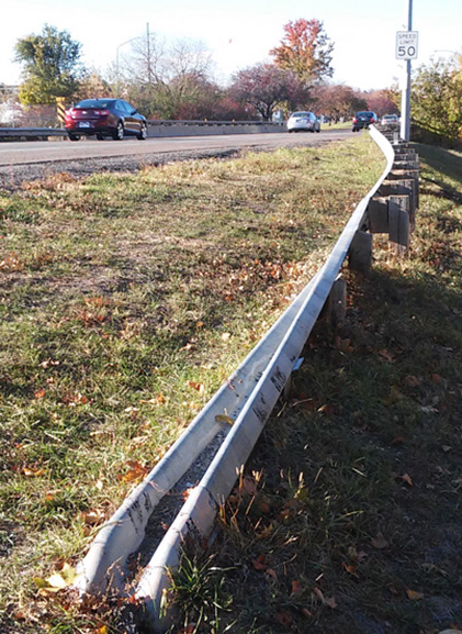
One approach engineers used to eliminate the blunt (or flared) end was to bury it in the ground. The W-bream could be “turned-down” onto its side. The beam would gradually drop vertically towards the ground and horizontally away from the pavement’s edge to where the end would be buried below existing ground (Figure 10). It created a cost-effective solution for many decades, but one with a serious flaw: The beam’s gentle vertical slope could serve as an unintentional ramp for a vehicle which has left the pavement which may vault the car over the barrier right into the very object the barrier was intended to protect the motorist from. Or it could act as a “railroad track” for an out of control vehicle, trapping it along its rail directing the car into the object of danger. This problem was addressed in 1990. The Federal Highway Administration (FHWA) issued a memoranda prohibiting the use of turning down ends for W-beam barriers [19] on all new roads and mandated damaged barriers be replaced with a modern barrier with crash-worthy terminals.
In 2011, a subcommittee meeting with the Transportation Safety Board (TRB) called for an “END [to] Turned-Down ENDs,” in which they criticized the use of flared ends and turn-downs and called on all countries to stop installing or implementing them on up-stream terminals [20]. While the United States has aggressively worked since 1990 to replace and remove turn-downs and flares, they are still in use in other countries [20].
Energy-Absorbing Terminals
Crashing into the end of a fixed barrier can be nearly as bad as crashing into the rigid object the barrier intends to protect motorists from. Shock-absorbing hardware is now mandated by FHWA on the terminal ends of all barriers, including W-beam and Jersey barrier (K-rail).
Modern roadway design mandates a crash cushion or other type of shock-absorbing terminal end be used. Specific standards vary from state to state, but FHWA does require the barrier be able to stop and deflect a passenger car or light truck travelling into it at 62 miles per hour [16](Figure 11).
These shock-absorbing ends vary from expensive high-performance collapsing metal attenuators to simple barrels of sand. Sand barrel arrays are useful for serious hazards that far away from the pavement’s edge and perhaps even outside the clear zone, but could still pose a serious threat to motorists who manage to wander far from the road [16].
The best are metal attenuators to redirect a vehicle’s inertia back toward the roadway. There are several system types available for state department of transportation(s) (DOTs) to purchase that use either a tangent or a flare to absorb crash energy and deflect a vehicle away from an obstacle [21].
Urban Curbs
Curbs offer a strong visual edge of pavement which helps a motorist pilot around corners. In very slow settings it offers some shielding of pedestrians and deflecting, but as speeds increase that attribute is quickly lost. Care needs to be taken in speeds above 50 miles per hour where a curb becomes a rigid obstacle itself. When a vehicle drifts into a vertically-facing curb at high speeds it may lose its center of gravity and roll. In all cases, a curb should never be used with a longitudinal barrier or an attenuating device as it can hinder their operation [22].
Breakaway Sheer Bolts
Sheer bolts offer an option in lieu of traditional wooden highway-sign posts. Wooden sign posts snap into pieces which reduces the force transferred to the impacting vehicle. Sheer bolts work similarly, especially when designing where a wooden pole isn’t an option, such as a street lamp (Figure 12).
AASHTO has recommended breakaway bolts since the 1970s. In 1985, the association began recommending states use breakaway mounting on all new light poles, signs, and other obstructions that must be within a clear zone. This was published in their publication “Standard Specifications for Structural Supports for Highway Signs, Luminaires, and Traffic Signals.” [23]
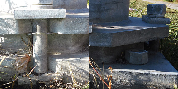
A lot of care needs to be put into the design. A street sign may not carry a heavy load but a light pole may. The base has to be structurally strong enough to support the pole during severe weather, like severe windstorms. Some early recommended designs were unable to support 50-foot steel poles [24]. The base can be overly strong since it remains in place while upper bolts and the post are sheered away.
Another matter of care designers take into account is when roadside slops exceed 1:6. A steep downgrade from the pavements edge may cause a motorist to strike the pole too high. Bolts may not sheer properly if a light pole is struck too high, typically above 28 inches [24].
Rumble Strips
Rumble strips are grooved patterns ground from the edge of the pavement just outside the edge line (Figure 13). A vehicle’s tires create a loud noise which alert a drowsy or distracted driver that their vehicle is steering off the
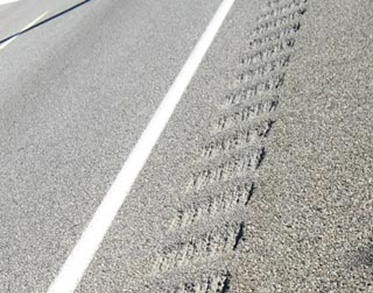
pavement. Rumble strips have been effective in reducing crashes [25].
Care should be taken to make sure rumble strip grooves do not make a shoulder unusable for cyclists. When grooves exceed the curvature of a bicycle tire, a cyclist will feel a noticeable vertical vibration which may cause a cyclist to lose control and fall into traffic [14]. If a rumble strip makes the shoulder unusable, a cyclist is more likely to ride inside a vehicle traffic lane. This could lead to motorists swerving or taking other risks that could cause them to lose control of a vehicle and end up off pavement.
Signs and Markings
Traditional
Traditional street signage, like speed limit signs, stop and yield signs, and guidance signs help make drivers aware of the law and, in so doing, make them aware of design features of the road which help them safely pilot regular or complex roadways in a safe manner. In addition to these regulatory and guidance signs are horizontal alignment signs and plaques which warn drivers that additional speed reduction may be needed or that the need to pay special attention to a curve. A set of pavement markings complaint with the “Manual on Uniform Traffic Control Devices” (MUTCD) can help a motorist know where to pilot a vehicle around a corner.
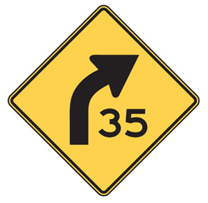
Advanced Warning
Advanced speed warning signs are governed by a speed table in the MUTCD. It takes into account the posted speed limit and the amount of speed reduction suggested by the sign (Figure 14). This gives a motorist, particularly of larger-classification vehicles that require more time to stop, adequate time to adjust their speed to navigate a curve without leaving the pavement [26].
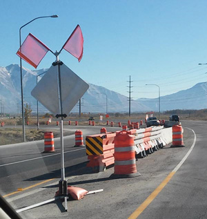
Construction Zone
A construction zone should take into account all of the above safety hardware, even if the safety hardware is temporary (Figure 15). This includes proper signs, longitudinal barriers, reducing or eliminating obstructions, and shock-absorbing barrier terminals. A construction zone should take into account proper temporary geometry, such as merge tapers and transition tapers [27].
CRASH STATISTICS
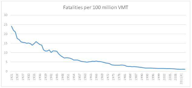
Fatal crashes have been declining in the United States over the past 90 years of recorded data. According to the National Highway Traffic Safety Administration (NHTSA), the total number of people killed on our highways is equal to what it was in 1949, but we travel nearly 7 times as many miles now as the country did in 1949 [28].
If fatalities are measured against the number of miles traveled, measured by 100 million vehicle miles traveled (100 MVMT), we see the number of fatalities fall from nearly 25 per 100 MVMT in 1929 down to 1.11 per 100 MVMT in 2013 (Figure 16).
CONCLUSION
Safety is not an accident. Surviving a serious off-pavement collision is more than just fate or good luck. It is the product of engineering – both modern, and by those whose contribution has long been forgotten but whose work lives on in the body of engineering knowledge.
This includes forgiving roadside hardware, such as longitudinal barriers, shock-absorbing crash attenuators, curbs, breakaway sheer bolts, and signs. It also includes taking care in the design to ensure the roadway’s curves can accommodate the posted speeds, a safe vertical shoulder slope, and adequate horizontal clear zone.
These design and construction changes correlate with an overall reduction in automobile fatalities. While car safety changes deserve much of the credit, credit is also due to changes to create a more forgiving roadside.
WORKS CITED
| [1] | S. Emery, “The Orange County Register,” 6 December 2010. [Online]. Available: http://www.ocregister.com/articles/pickup-278976-truck-chp.html. [Accessed 9 November 2015]. |
| [2] | J. H. L. H. D. T. R. D. Powers, “The “Forgiving Roadside” Design of Roadside Elements,” Transportation Research Board, 2013. |
| [3] | American Association of State Highway Transportation Officials (AASHTO), “Manual for Assessing Safety Hardware (MASH),” inManual for Assessing Safety Hardware (MASH), American Association of State Highway Transportation Officials (AASHTO), 2011. |
| [4] | F. L. Torre, “Improving Roadside Design to Forgive Human s: Forgiving Roadside Design Guideline,” inRoadside Safety Design and Devices: International Workshop, July 17, 2012,, Milan, Italy, Transportation Research Board (TRB), 2013, pp. 66-74. |
| [5] | AASHTO, “2.3.6 Speed,” inA Policy on Geomentric Design of Streets and Highways, American Association of State Highway Transportation Officials (AASHTO), 2011, pp. 2-53. |
| [6] | AASHTO, “Sight Distance: General Considerations,” inA Policy on Geometric Design of Highways and Streets, American Association of State Highway Transportation Officials, 2011, pp. 3-2. |
| [7] | AASHTO, “Minimum Radius,” inA Policy on Geometric Design of Highways and Streets, American Association of State Highway Transportation Officials, 2011, pp. 3-31. |
| [8] | AASHTO, “Minimum Turning Path,” inA Policy on Geometric Design of Highways and Streets, American Association of State Highway Transportation Officials, 2011, pp. 2-10 and 2-18. |
| [9] | AASHTO, “Maximum Superelevation Rates for Streets and Highways,” inA Policy on Geometric Design of Highways and Streets, American Association of State Highway Transportation Officials (AASHTO), 2011, pp. 3-30. |
| [10] | AASHTO, “Lane Widths,” inA Policy on Geometric Design of Highways and Streets, American Association of State Highway Transportation Officials (AASHTO), 2011, pp. 4-7. |
| [11] | AASHTO, “Roadside Design,” inA Policy on Geometric Design of Highways and Streets, American Association of State Highway Transportation Officials (AASHTO), 2011, pp. 2-84. |
| [12] | AASHTO, A Policy on Geometric Design of Highways and Streets, American Association of State Highway Transportation Officials (AASHTO), 2011. |
| [13] | AASHTO, “Highway Safety Design and Operations Guide,” American Association of State Highway Transportation Officials (AASHTO), 1997. |
| [14] | CEDR, “Forgiving Roadsides Design Guide,” Conference Europeenne de Directeurs des Routes (CEDR), 2013. |
| [15] | “New Jersey Median Barrier History,” Roads to the Future, 22 November 1997. [Online]. Available: http://www.roadstothefuture.com/Jersey_Barrier.html. [Accessed November 2015]. |
| [16] | Federal Highway Adminstration (FHWA), “Frequently Asked Questions: Barriers, Terminals, Transitions, Attenuators, and Bridge Railings,” 30 September 2015. [Online]. Available: http://safety.fhwa.dot.gov/roadway_dept/policy_guide/road_hardware/qa_bttabr.cfm. [Accessed 10 November 3015]. |
| [17] | Federal Highway Administraion (FHWA), “W-Beam Guardrail,” 2015. [Online]. Available: http://safety.fhwa.dot.gov/roadway_dept/policy_guide/road_hardware/ctrmeasures/wbeam/. [Accessed 10 November 2015]. |
| [18] | National Research Council (U.S.). Highway Research Board, “Special Report – Highway Research Board, Issue 81,” 1964. [Online]. Available: https://books.google.com/books?id=pk5NAAAAYAAJ&focus=searchwithinvolume&q=%22until+further+research%22. [Accessed 11 November 2015]. |
| [19] | Federal Highway Administration (FHWA), “Memorandum,” 29 September 1994. [Online]. Available: http://safety.fhwa.dot.gov/roadway_dept/policy_guide/road_hardware/policy_memo/memo072994/. [Accessed October 2015]. |
| [20] | M. Dreznes, “END Turned-Down ENDs,” inTransportation Research Circular, 2013, pp. 75-82. |
| [21] | Federal Highway Administration (FHWA), “Supplementary Guidance for the Selection of W-Beam Barrier Terminals,” 17 November 2005. [Online]. Available: http://safety.fhwa.dot.gov/roadway_dept/policy_guide/road_hardware/policy_memo/memo1105a/. [Accessed 10 November 2015]. |
| [22] | NYDOT, “Chapter 10: Roadside Design, Guide Rail and Appurtenances,” inNew York State Highway Design Manual, 10-39, State of New York Department of Transportation, 2012. |
| [23] | American Association of State Highway Transportation Officials (AASHTO), Standard Specifications for Structural Supports for Highway Signs, Luminaires, and Traffic Signals, AASHTO, 1985. |
| [24] | Texas Department of Transportation, “Section 3: Breakaway Light Poles,” Texas Department of Transportation, 1 November 2003. [Online]. Available: http://onlinemanuals.txdot.gov/txdotmanuals/hwi/breakaway_light_poles.htm. [Accessed 11 November 2015]. |
| [25] | AASHTO, “4.5 Rumble Strips,” inA Policy on Geometric Design of Highways and Streets, American Association of State Highway Transportation Officials, 2011, pp. 4-14. |
| [26] | FHWA, “Section 2C.05 Placement of Warning Signs,” inManual on Uniform Traffic Control Devices, US Department of Transportation – Federal Highway Administration, 2006, p. 108. |
| [27] | FHWA, “Section 6C.05 Transition Area,” inManual on Uniform Traffic Control Devices, United States Department of Transportation – Federal Highway Administration, 2009, p. 554. |
| [28] | NHTSA, “Fatality Analysis Reporting System,” National Highway Traffic Safety Administration (NHTSA), 2013. |